WIRE DIAGRAMS STARTING MOTOR USING AUTO-TRANSFORMATOR

Wire Diagrams Starting Motor Using Auto-Transformer - In the starting mode, the initial voltage supplied to the motor through a reduction autotransformator and after a few seconds the motor steady speed is reached, the voltage to the motor stator terminal voltage value is returned to positions normally through displacement contact circuit as shown in the picture below. 
Wire Diagrams Starting Motor Using Auto-Transformer

The process that occurs on the motor with autotransformator starting mode consists of three stages as follows:

Stage One
when subjected to early start the motor terminal voltage supply whose value has been reduced because the flow of power to the motor is passed through a autotransformator connected in star. The amount of reduction in the voltage applied to the motor depending on the position of tapping on the autotransformator rolls.  

Stage Two
after the motor spins while, contactors that form the star relationship autransformator detachable, so the auto transformer will form a series inductance in series with the motor, in this case actually rolls the autotrasnformator form a series inductor series with the stator windings. Usually the transfer of the first stage to the second stage will be to work after a few seconds the motor rotates.

Third Stage
a split second after the second stage, the circuit will move ketahap third. At this stage supply voltage the motor gets in full accordance with the voltage nets - nets. When the contactor which sends a full supply voltage to the motor terminals is active, then indirectly autotransformator ter-bypass so that the existence autotrasnformator not affect the value of the supply voltage towards the motor. And if the motor has been operating normally, autotransformator can be turned off.

Starting the system with this mode is typically used on LV motors with power above 150kW. Disadvantages of this system is the cost is quite expensive because of the high cost for a autotransformator. 

Related Posts:

3RDITEK HEADBAND, NEW TREND WEARABLE DEVICE

3RDITEK Headband, new trend wearable device - Are you including typical adventurers who like to explore new places, or perhaps typical of the existent always wanted moment is not enshrined in any occasion? When this has been a lot of gadgets mapun wearable device that supports your hobby to snap snap. Most can use a smartphone that has mushroomed today. Plus tongsis can also, or by taking action camera also legitimate legal only. Who want a more pro can use the Drone with the functionality and quality is very diverse.
3RDITEK Headband, new trend wearable device

Besides all that, there is a new trend wearable device, which headband. Yes, a device used in our forehead and right in the middle there is a camera. The model could in the analogy like a headband. Is 3RdiTek who developed this device as 3RDi, because users will look like as the third eye (third eye).

3RDi is a yag camera will record every precious moment you want to preserve. Such as action camera, photos and videos can be easily retrieved. Simply pair your head, and do touch slide (slide) to start recording a video. If you want to capture images with flash simply by tapping the left side of the headband, whereas if you do not want to use flash then simply tap the right side of the headband 3RDi. Easy enough right? 3RDi HD camera equipped with the ability to record up to 1080p resolution with wide view mode.

This device is compatible with Android and iOS. And reminds us of Google Glass that has similar functionality but with more complex features. 3RDi the model itself is not bad and suitable for use as an accessory, but the concept was introduced models try not to everyone's taste, especially for men, because too flashy camera in munculkan by the Headband. In contrast to what Google Glass tried to offer a more elegant and classy, especially the camera features a slightly disguised.

Related Posts:

FACEBOOK RELEASE TELEPORTATIONS TOOL IN 2025

Facebook Release Teleportation Tool In 2025 - Technology continues to grow rapidly, communication technology is also growing rapidly. Communication tools such as mobile phones or who currently has mushroomed is a smartphone has become a trend and lifestyle, because the more cheap and easy to obtain smartphone. But the trend does not just stop human communication to voice communication only. Mike Schroepfer as Head Technician Facebook recently revealed a plan to make human nanar communication easier and a lot of aspects that can be reached, the tool teleportation. In a statement, Schroepfer said "Facebook wants to build a tool that lets anyone can go to the desired place with the exclusion of geographic boundaries." It is said, means of teleportation will be completed in 10 years, which is expected to be introduced to the public in 2025.
Facebook Release Teleportation Tool In 2025
Facebook Release Teleportation Tool In 2025

Unfortunately, teleportation tool is not as teleportation tools that exist in science fiction films, which can move a person from one place to another in an instant. Transport equipment developed based on Virtual Reality Facebook, the Oculus. Mike Schroepfer give you an idea, Oculus will be able to make the user think the virtual world is real, imitating the world in real-time and allows users to realize the imagination in 3D. In other words, the virtual world who want carried Facebook will not feel fake as it is today. One of the great challenges that make the virtual world feels real is it possible to see oneself, for example, saw a hand or other body parts. Hmm, seemed steeped in the movie The Matrix or Inception.

Very interesting would plan to make up the teleportation tool. The future will definitely be a lot of development and institution or other scientists who will meyempurnakan concept and idea of this Facebook artificial Teleportation. And it is not likely one will be found when the actual teleportation tool menindahkan people to the desired place in an instant.

Related Posts:

METALLIC SHEATHING IN POWER CABLE TECHNOLOGY

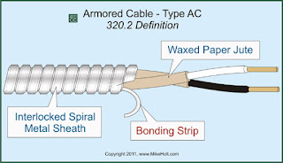
Metallic Sheathing In Power Cable Technology - metallic sheating is provided over the paper isulation and should have intimate contact with the external layer of insulation. the metallic layer provided must be electrically contionous. thus, the sheath used not only provide waterproof protection, but also provides an electrical earth shield the potential of which is zero and the potential of the conductor is reffered to this.
Metallic Sheathing In Power Cable Technology

the metallic sheath used may be either of lead or lead alloy or of aluminium.

Lead and lead alloy
are the mostly used materials as the facilitate the manufacturing of cables and is pliable. also lead is generally immune to corrosion except under secial conditions (by electrolytic action and organic acids). however, lead may crack due to inter-crystalline corrosian and vibration. it has been observaed that the cables laid underground where heavy traffic passes and near the railway lines, bridges etc. the cables fail due to such cracks.

Aluminium Sheath
In recent years aluminium has also been used a sheath, since it decreases the weight of the cable (lead is about four times heavier than aluminium) and its conductivity is about seven times that of lead which make such cable much adaptable for mining works. It may be pointed out that the sheath loss increases due to increases in sheath current. the current rating for the multicored aluminium sheathed cables is the same as that for lead-sheathed cables for the same conductor temperature but the single core aluminium sheathed cables used on a.c system are derated due to increase in sheath current.

The following are the advantages of the aluminium sheathed cables over the lead sheathed cables:
  • Increase in the tensile strenght.
  • The Weight  is decreased which facilitates in handling of the cable in its installation.
  • since the cable is of light weight, so the fixtures will also be light.
  • The cable is free of cracking due to vibration etc.
  • It improves the mechanical properties of the cable and reduces the need of heavy armouring.
Sometimes with lead sheathed cables an earth continouly conductor is run which is in good contact with the sheath throught its length to ensure adequate earthing.

Related Posts:

CABLE INSULATION IN POWER CABLE TECHNOLOGY


Cable Insulation In Power Cable Technology - Cable is a medium to deliver electrical energy. in an electrical wiring generally consists of an insulator and a conductor. Isolator is a cable wrapping material is generally made of plastic, while the conductor is made of copper or aluminum.
Cable Insulation In Power Cable Technology

Cables are usually classified according to the type of insulation used. the type of insulation to be used must have the following properties:
  • it should have specific resistance.
  • it should have high dielectric strength
  • it should be tough and flexible.
  • it should not be hygro:copic i.e. it should not absord moisture from air or surroundings.
  • it should be capable of standing high temperatures without much deterioration.
  • it should be non-inflamable.
  • it should not be attacked by acids or alkalies.
  • it should be capable of withstanding high rupturing voltage.
Althought it is not possible to have all the above mentioned qualities in one particular type of insulation. the selectionof a particular type of insulation to be used is dependent upon the purpose for wich the cable is required and qualities of the insulation to be aimed at. the following are the chief types of insulation groups wich can be used:
  • Rubber.
  • Polyethylene.
  • polvinyl chloride (P.V.C)
  • Fibrous material such as paper or jute.
  • Vulcanized bitumen.
  • Gutta-percha.
  • Silk, Cotton, enamel.
Rubber 
Rubber is the most commonly used insulation in cables. Rubber has a dielectric constant between 2 and 3, dielectric stress is 350 kV/cm. approximately, and spesific resistance of 10^17 Ohm/cm. It absorbs moisture slightly and the maximum safe temperature is approx. 38 C. So, pure rubber cannot be used as an insulation since it cannot withstand high temperatures and cannot be put to rough usage, being too soft. Thus, mostly the rubber used as an insulation on wires consists of 20 to 40 per cent of India rubber, the remainder being mineral matter such as zinc oxide, red lead etc. also a little bit of sulphur is added. the method of applying insulation is given below.

Polythylene
It is thermoplatic synthetic resin and has very good dielectric and ageing properties. it is a tough and flexible material having exelent electrical and mechanical properties as an insulating material. It has a dielectric strength of 400 kV per cm. Polyethelene is non-imflamable material. Even if a flame is continously applied to the polyethylene. the buraing will stop after a burning will stop after a few oms. away  from the flame. due to threre proporties it is being extensively used as an insulation.

Polyvinyl-Chloride
It is a thermo-plastic synthetic resin and is being widely used as an insulation. it has high electrical resistivity, good dielectric strenght and mechanical toughness over a wide range of temperture. moistures acids and alkalies do not affect P.V.C. insulated cables are usually employed for medium and low voltage domestic industrial lights and power instalations.

Paper
 paper insulation in power cable has almost superseded the rubber insulation. the foremost reason of this is that it is quite cheap and has low capacitance and high dielectric strength.

Related Posts:

CABLE COSTRUCTION IN POWER CABLE TECHNOLOGY

Cable Construction In Power Cable Technology - Cable is a medium to deliver electrical energy. in an electrical wiring generally consists of an insulator and a conductor. Isolator is a cable wrapping material is generally made of plastic, while the conductor is made of copper or aluminum.
Cable Construction In Power Cable Technology

The ability of the electrical conductivity of the cable is determined by CRC (current-carrying capability) has, where electrical conductivity parameters specified in units of Ampere. Current-carrying capability is determined by the cross sectional area of the conductor that is in electrical wiring.

The general construction of the cable is given below:
  • Core, All cable have one central core or a number of cores of stranded copper or aluminium conductors having highes conductivity. Generally there are one, twoe, three or four cores.
  • Insulation, THe different insulation used to insulate the conductors are paper, varnished cambric and vulcanized bitumen for low voltage, but mostly impregnated paper is used which is an excellent insulating material. when vernished cambric is used as an insulating material (for low voltage cables) petroleum jelly is aplied between the alyes of the cambric tape wich prevents demage to the insulating tape due friction when the cable are handled.
  • Metalic Sheath. A metalic sheath  is provided over the insulation so as to prevent the entry of moisture into the insulating material. The metalic sheath usually of lead or lead alloy and in case of cables having copper as conductor sometimes aluminium is also used for providing metalic sheath.
  • Bedding, Over the metalic sheath comes a layer of bedding wich consists of paper tape compounded with a fibrous material. also sometimes jute strands or hessian tape (Strong coarse cloth of hemp or jute) is also used for bedding. the purpose of providing the bedding is to protect the metalic sheath from mechanical injury for the armouring.
  • Armouring. Armouring is provided to avoid mechanical injury to the cable and it consists of one or two layers ofgalvanised steel wires or two layers of steel tape.
  • Serving, Over and above armouring a layer of fibrous material is again provided which is similar to that of bedding but is called as serving.

Related Posts:

HOW THE PROCESS OF MANUFACTURE OF ELECTRIC MOTORS

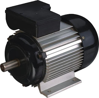
How the process of manufacture of electric motors - Today I will share how to process the electric motor is produced. for those of you who do not know what the bike, I will give a little knowledge. The electric motor is a tool that serves to convert electrical energy into mechanical energy. Electric motors used in home appliances such as fans, washing machines, water pumps and vacuum cleaner. in addition to the electric motor is also used in the industrial world as a weight lifter, pengengkut load on conveyors and others.
How the process of manufacturre of electric motors


Electric motor consists of diverse types and type. All kinds of electric motors has two main parts: the stator and the rotor, stator is the stationary part of the electric motor and the rotor is part of an electric motor that moves (spins). Based on the work voltage source is used, the electric motor can be divided into 2 types:
  • Direct current electric motor
  • alternating current electric motor  

Working Principles
In the electric motor, electrical energy is converted into mechanical energy. This repair is done through a process of induction or commonly referred to as an electro magnet. poles of a magnet that will repel namesake and poles are not namesake, attraction. Then we can get the movement if we put a magnet on a rotatable shaft, and the other magnet in a fixed position.

actual manufacture of electric motors can also be assembled, but the results of the motor assembly is very simple so it can not be used in large power. Now I will share the process of making the bike itself is done at the company. where these motors can be used for heavy loads.

Related Posts:

>